

The power for a car’s electrical system comes from the battery, but it must be constantly replenished by a generator. Up until the early 1960s, a DC generator, which is technically called a dynamo, was the standard. The physical principle by which any electrical generator works is called the Lorentz force. You’ll probably never need to remember that name, but it’s good to remember the concept.
When an electrically charged particle, such as an electron, passes through an orthogonal magnetic field, it experiences an orthogonal to both the magnetic field and the direction of travel. If a metal wire passes through an orthogonal magnetic field, the electrons on the atoms making up the metal are pushed along the wire, giving rise to a current or voltage.
In a generator, the magnetic field is supplied by electromagnetic winding segments, comprising the stator and fixed to the inner surface of the housing. These windings are supplied with current from the generator output. The moving wires that pass through the field are wound in coils which form the armature and is located on the rotating generator shaft. The armature windings terminate on conducting segments of a drum near the end of the shaft. The segmented drum is referred to as the commutator. The entire rotating assembly is called the rotor. The current is then carried to the output by stationery conducting brushes which make contact with the commutator segments as they slide by. The generator can be operated with either polarity, depending on the polarity of the magnetic field from the stator. Therefore, the cores of the stator magnets will remain magnetized for only a limited time without current flow.
Polarizing is done with the engine turned off and momentarily connecting a jumper wire between the battery source terminal and the generator output. This allows a brief field current to flow and magnetize the iron stator cores in a direction consistent with the battery polarity.
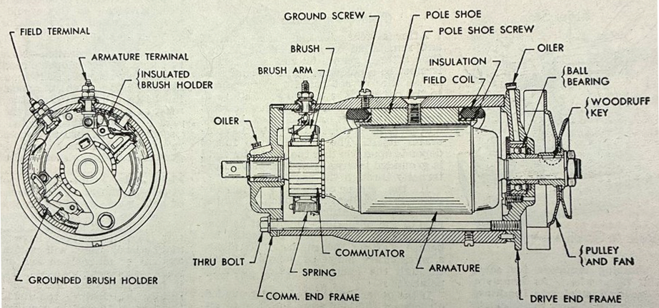
Up until the early 1940s, generators were equipped with a “cut-off” which was effectively an electromechanical diode in series with the output. Its function was to allow current to flow from the generator to the battery, but not the other way. This prevented the battery from losing charge through the generator when the engine was off. Polarizing could be accomplished by using a jumper wire to short circuit the cut-out, allowing the battery to momentarily activate the field current of the stator.
Starting in the late 1930s, generators were equipped with a voltage regulator instead of a simple cutout. The regulator regulates the current to the stator to match the output current to that needed to keep the battery charged without overcharging. It does this as well as performing the role of a cutout to keep the battery from discharging through the generator. To polarize a generator with a voltage, the jumper wire should be momentarily connected between the battery (B) and armature (A) terminals of the regulator.
Starting in 1960, generators were displaced alternators. These are AC generators with built-in transistor rectifiers to convert the output to DC. That’s a whole different subject that we can talk about some other time.
Leave a Reply