
Guest W. Jones this month shows you how to…..
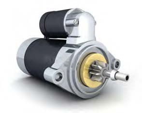
The starter motor is heavy, sturdy and unlikely to get much attention, but a faulty one will be a real headache. Often located in the depths of the engine bay, making it hard to access even in a workshop, it’s not the sort of component that you want to be trying to remove and dismantle at the roadside. There are two types of starter motors: inertia and pre-engaged. Inertia units are common to most 1960s (and earlier) classics, and work by spinning a Bendix gear that drives itself up the main shaft and engages with the ring gear. If it doesn’t engage, you’ll hear a distinctive metallic grating sound – it cranks the ring gear around. As the engine fires, the excess speed forces the Bendix gear out and a spring re-turns it home.
Pre-engaged starters are more sophisticated, with a solenoid that pushes the Bendix to engage with the ring gear, before another solenoid supplies power to the starter and gets it to turn over. We’re focusing on the inertia version here, but the procedure is largely similar for either variant. With a tear-down, a cleaning and inspection, plus a fresh set of bushings and brushes, your starter should be good to crank away for years to come.
First take off the brush cover plate and pry the brush spring clips from their posts in the brush cage. Two brushes will be connected to the backplate and another pair to the coil windings. Undo the nuts from the electrical connection tower and make a note of any insulator collars for reassembly.
Remove the two long bolts on the rear of the starter and both cover plates and casing should come away from the arma-ture, which will be secured to the front plate. Be sure to mark with a prick punch for reassembly. Take it apart carefully and make a note of the number and location of any shims, thrust washers or nylon collars that come out with the shaft.
Compress the Bendix spring using grips and pry out the retaining circlip and locating pin. The assembly should slide off, but may have a Woodruff key that can fall out. Note the order of assembly for later. The armature should now be removable through the front plate. Thoroughly clean off any grease.
Inspect the condition of the insulation on the coil windings, which should be intact and free from moisture or corrosion. A specialist can re-varnish the windings if needed. The pole shoes around the coil should be clean and rust-free, and can be bead-blasted, but take care not to damage the windings.
If there’s any movement between the armature shaft and the bushings, then the latter need to be replaced. Carefully drive out the old bushings with a socket that’s roughly the same size. Soak the new ones in oil for 24 hours before gently pressing them in with a vice. Ensure that the shaft spins freely in the new bushings.
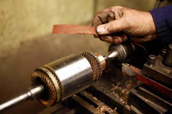
Using emery paper, clean the surface of both the winding ‘pack’ (the shiny steel area towards the center of image left) and the commutator ring (to the right). Spinning them in a lathe is best, but be careful not to take off more than light surface corrosion. Clear the end casings of any grease or oil.
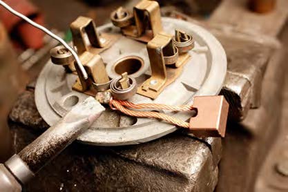
Brushes often have a maximum wear mark, typically about 1/3 inch deep. They need to be unsoldered from the terminal post, with the brushes often paired. They’re identical, but ‘earth’ brushes usually go on the end casing and don’t need to be insulated, while the ‘field’ coil brushes are on the main casing.
Carefully inspect the Bendix gear. It’s a wearable item (made from mild steel, unlike the hardened flywheel ring gear), but the teeth should all be intact. You can clean worn edges on a grinder, but replacement is best.
Leave a Reply